
AFM tip radius, geometry and resolution
In atomic force microscopy (AFM), a smaller tip apex can help reveal finer lateral detail, but tip radius alone does not determine image resolution. The whole tip must reach the surface, the image must sample it adequately and the feedback must follow it.
Published by Tiny Infinities · 21 September 2026
Updated 25 September 2026
Separate lateral detail from height measurement.
Lateral resolution is the ability to distinguish nearby features across the surface. Vertical sensitivity concerns small height changes; it does not establish height accuracy.
An isolated particle can appear wider because the tip sidewall meets it before the apex reaches its edge. Its height may still be measured if the tip reaches both the surrounding surface and the particle top. Calibration, tracking and sample deformation can also affect that height. MikroMasch’s geometry examples illustrate the distinction.
Check whether the tip can reach the feature.
The apex radius describes curvature near the tip’s end. Opening angle, length and sidewall shape determine access further up the tip. A sharp but broad tip may not enter a narrow trench, making the trench appear shallower than it is.
This geometric effect can broaden protrusions and narrow depressions. It is often called tip convolution; NIST’s geometric treatment explains how tip and sample shapes combine in an image.
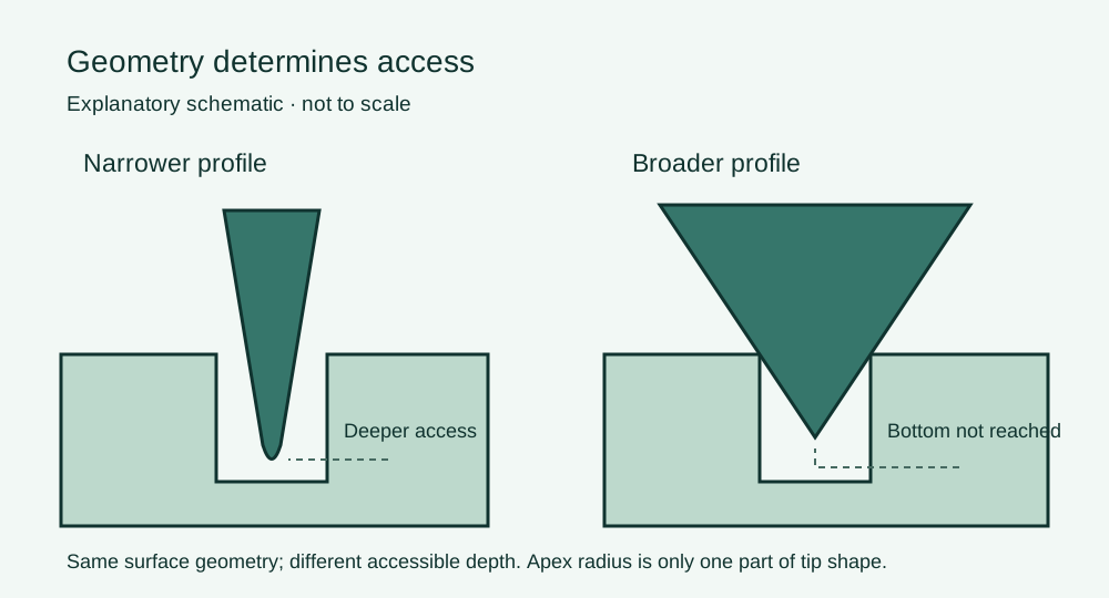
Read geometry descriptions together.
- Apex radius: local curvature at the end of the tip.
- Side profile: how the tip widens away from the apex.
- Aspect ratio: height relative to width. State which dimensions are used for a numerical comparison.
- Circular symmetry: an ideal shape that is unchanged by rotation around its axis. This describes shape, not sharpness.
Feature access also depends on the usable tip length and its mounted orientation. A single geometry number cannot describe all of these constraints.
Set scan size, sampling and feedback together.
Pixel spacing is the distance between recorded points, not the smallest feature the probe can resolve. A 5 µm scan with 512 points across a line has a nominal spacing of about 10 nm. More pixels cannot reveal a surface the tip never reaches.
The feedback adjusts tip–sample position to maintain the selected interaction. Unsuitable speed or feedback settings can distort a feature. Compare forward and reverse scans and retain the settings when investigating a suspected geometric limit. The faster-scanning guide explains the system limits.
Read roughness alongside the height image.
Roughness summarises height variation over a chosen area. Record the metric, scan size, sampling and processing: levelling, line corrections and filtering can change the result.
A broader or contaminated tip may miss fine valleys, changing the measured roughness even on an unchanged sample. Compare images and profiles under consistent conditions, and check tip condition before attributing a change to the surface.
Describe the feature before choosing a probe.
- Particles or ridges: decide whether you need height, width or separation between objects.
- Trenches or pits: describe the opening width, depth and sidewall slope.
- Roughness: define the area and scale of variation that matter.
PolarTip combines a measured 5 nm apex radius with a circularly symmetric design and high aspect ratio. To discuss its fit, share the feature dimensions, sample material, instrument and AFM mode.